
Last updated: October 27, 2026
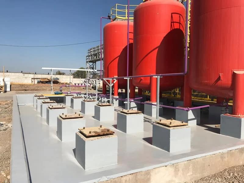
Most containment walls do one job. A precast containment structure is usually asked to do two.
In Alberta, a containment wall can be the dike. It can also be the impervious barrier the dike is supposed to sit on. When one element does both, the joints stop being construction details and become acceptance items. The volume rule is arithmetic. The two-job question is where projects get sent back.
What the structure has to hold
Start with capacity, because it sets the footprint before anything else does.
AER Directive 055 sets containment capacity by requirement, not by rule of thumb. For a single storage device, capacity must be not less than 110 per cent of the device’s capacity, plus the displacement volume of any structures inside the containment, including piping and granular layers below dike height (requirement 136). The displacement clause is the one most often missed. Pipe supports, pump skids and gravel all take up room that the spill needs.
For more than one device, capacity must be at least the largest device’s capacity plus either 10 per cent of the largest device’s capacity or 10 per cent of the aggregate capacity of all other devices, whichever is larger (requirement 137). Displacement is counted here too.
Two thresholds remove the obligation or change it:
| Condition | Effect |
|---|---|
| Total combined on-site volume up to 5 m³ | Storage permitted without secondary containment (Directive 055, sections 3.2 and 4.2.1) |
| Double-walled tank with continuous, monitored interstitial space | Secondary containment not required where the space is monitored under section 4.3.4 (requirement 31) |
| Temporary storage, under three months and under 3,000 m³ combined | Diking optional; a one-metre-high impervious berm is an alternative. Total storage must not exceed one year (section 4.2.2, requirement 147) |
Everything else gets a containment structure.
When the concrete is allowed to be the barrier
Directive 055 allows dike walls made of soil, steel, concrete, solid masonry or synthetic material (requirement 133). The same requirement goes further: a concrete or steel containment structure forming a walled impervious barrier may serve as both the dike wall and the liner, including bins used for small tanks.
That is the permission precast is built around. Instead of an earth dike with a clay or synthetic liner keyed into it, the structure itself is the barrier.
The trade is strict. The wall must have no openings, must contain fluids within the diked area, and must withstand hydrostatic pressure at full capacity (requirement 134). Openings are allowed only where the penetration connects directly to a storage device, or where it is a maintenance access door. Either way it must be hydraulically sealed and designed to resist settlement and fire-exposure stresses.
Note the limit on the other side. Concrete is not acceptable as primary containment where liquids are stored (requirement 26). The structure holds the spill. It does not hold the product.
The joints and the penetrations
If the concrete is the barrier, every joint is part of the barrier.
The federal Code of Practice for Storage Tank Systems states the same idea from the liner’s point of view. Where an impermeable barrier is used, it is sealed to the tank or pad perimeter when it is not installed under the tank, and it extends to the top of the dyke wall (section 3.9.2(1)). A barrier of non-conforming design must be compatible with the stored product, acceptable to the authority having jurisdiction, and achieve a maximum hydraulic conductivity of 1 x 10⁻⁶ cm/s (section 3.9.2(2)).
Penetrations get their own rule. They must be located at the high point or in a raised part of the dyke floor, and all liner penetrations shall be sealed (section 3.9.3).
Directive 055 sets the comparable figures for a liner-based system: a synthetic liner at 10⁻⁶ cm/sec or less with a minimum thickness of 30 mil, or compacted or natural clay at 10⁻⁶ cm/sec or less in situ, or 10⁻⁷ cm/sec or less in the laboratory, with a minimum thickness of 0.6 m (requirement 110).
A precast structure removes the clay or synthetic layer from the drawing. It does not remove the performance that layer was there to deliver. The joint detail, the waterstop and the sealant now carry it.
The floor, the sump and the water that is not a spill
Containment collects weather as well as product.
Directive 055 requires the area to be graded to a sump or low point to collect rainwater, snowmelt and any leakage (requirement 143), and requires the site to be contoured so surface water does not collect immediately around the containment system (requirement 132). There is no uncontrolled discharge of collected fluids, and no discharge of untested fluids; surface discharge requirements in section 5.4 come first (requirement 144).
The Code of Practice gives the slope. Containment area floors within dykes shall slope away from the tank base towards a sump at a slope greater than 1 per cent (section 3.10.2). Where an oil-water separator handles the collected water, it is sized for a 10-year, one-hour storm, or meets performance criteria of no more than 15 mg/L free oil and grease, a design oil specific gravity of 0.875 ±0.025, and retention time sufficient to separate 60-micron droplets (section 3.10.3).
Slope-to-sump is a precast design input, not a site fix. Tell us the sump location before the panels are cast.
Where three Canadian authorities state the same rule three ways
The multi-tank volume rule is worth reading carefully, because three Alberta and federal sources word it differently.
| Source | Multi-device wording |
|---|---|
| AER Directive 055, req. 137 | Largest device, plus the greater of 10% of the largest device or 10% of the aggregate of all others |
| ECCC Code of Practice, s. 3.9.1(1) | Largest tank, plus 10% of the greater of that single-tank capacity or the combined capacity of all other tanks |
| Alberta Agriculture Agdex 769-1, s. 7 | The greater of 110% of the largest tank, or the largest tank plus 10% of the total volume of the remaining tanks |
They converge on 110 per cent for a single tank. They do not produce identical numbers on every multi-tank layout. We do not average them and we do not pick one. Which document governs is a determination for your regulator and your engineer, not the plant. Tell us the governing figure and we size to it.
The agriculture guidance confirms the material list from the farm-site end: materials should be non-combustible and impermeable, such as compacted clay, concrete or steel. It sets earth-dike geometry at a flat top not less than 600 mm (2 feet) wide and at least 600 mm (2 feet) high. A precast wall replaces that earth section with a vertical face and gives the footprint back.
Standards we name and do not quote
Several documents that govern this work are not public.
The National Fire Code (Alberta Edition) carries the separation distances. Directive 055 requirement 23 says adjacent storage systems, including the dike wall, must be spaced to prevent further damage if one fails, and refers to section 4.3.2 of that code for minimum distances. The directive does not state the distances, and neither do we. Requirement 33 also sends foundations and supports to the fire resistance rating in section 4.3.3.1(3) of the same code, and requires them to minimize differential settlement and corrosion.
ULC/ORD-C142.15, Precast Concrete Tanks, exists and is the recognised product standard in that family. The Code of Practice likewise names ULC-S653, ULC-S655, ORD-C142.5, ORD-C58.9 and ORD-C142.20 for tanks and barriers.
We name these. We do not reproduce numbers from them. Confirm any figure that matters to your design against the governing edition.
Ordering: what the plant needs
Send these and we can quote without a second round.
- Governing regulator and document for the site.
- Stored product, and whether any of it is a liquid under the primary containment rule.
- Number of storage devices, each capacity, and the required containment volume as determined by your engineer.
- Displacement volume of piping, supports and granular layers below dike height.
- Plan dimensions available, and any setback the site imposes.
- Required wall height, and whether a maintenance access door is needed.
- Every penetration: size, elevation and what it connects to.
- Sump location and the floor slope you are designing to.
- Whether the structure is required to act as the impervious barrier, or sits on a separate liner.
- Fire resistance requirement, if the authority having jurisdiction has set one.
- Site access for delivery and crane setup.
- As-built drawing requirements. The Code of Practice requires as-built drawings showing the secondary containment systems, and revised as-builts after alteration (sections 3.2.7 and 3.7.2).
Lead time
Three things set lead time, in this order: standard panel section or custom cast, penetrations cast in or field-cut, and whether a sealed-drawing review sits in the path.
Cast-in penetrations add drafting time and remove field risk. Field-cut penetrations do the reverse, and under requirement 134 a field-cut opening still has to end up hydraulically sealed. We have built containment work in Alberta for decades, and the pattern holds: projects that fix penetration locations before casting ship on the first schedule.
What this does not solve
The structure holds a spill and proves it is impervious. It does not monitor, inspect or maintain itself.
Directive 055 requires the diked area to be kept in good condition and free of weeds, debris and extraneous combustible material (requirement 139), and does not allow a lease berm to replace a dike unless the AER has authorized it (requirement 140). Devices within 100 m of a water body or permanent stream, or where a spill could reach water, require a barrier or a plan submitted to the AER (requirement 146). None of that is a product feature.
Where this article stops
This article covers the containment structure as a precast product: capacity, the two-job wall, joints, penetrations, floor slope and ordering.
It does not cover tank selection, interstitial monitoring equipment, leak detection systems, cathodic protection, or the separation distances held in the National Fire Code (Alberta Edition). It does not state the acceptance criteria of any paywalled standard. It is not a design and it is not a regulatory determination. The governing requirement for your site comes from your regulator and your engineer.
For the sectors this work usually lands in, see our solutions overview. For related structures, see precast box culverts in Alberta and how precast panels are installed. For the wider civil picture, see how infrastructure uses precast concrete.
FAQ
Can a precast concrete wall be both the dike and the liner? Yes, under AER Directive 055 requirement 133, a concrete or steel containment structure forming a walled impervious barrier may serve as both, including bins for small tanks. The wall must have no openings, contain fluids within the diked area and withstand hydrostatic pressure at full capacity.
How much volume does secondary containment have to hold in Alberta? For a single storage device, not less than 110 per cent of its capacity plus displacement volume, under Directive 055 requirement 136. For multiple devices, requirement 137 applies and the wording differs between the provincial and federal documents, so confirm which governs your site.
Is there a size below which containment is not required? Directive 055 sections 3.2 and 4.2.1 allow up to 5 m³ total combined on-site volume without secondary containment. Double-walled tanks with a continuous, monitored interstitial space are addressed separately under requirement 31.
Can concrete be used as primary containment? No. Directive 055 requirement 26 states that concrete is not acceptable as primary containment where liquids are stored. It is used for the containment structure around the storage device.
What slope does the containment floor need? The federal Code of Practice, section 3.10.2, requires containment area floors within dykes to slope away from the tank base towards a sump at a slope greater than 1 per cent. Directive 055 requirement 143 requires grading to a sump or low point.
How are penetrations handled? Penetrations must be located at the high point or in a raised part of the dyke floor and all must be sealed, under Code of Practice section 3.9.3. Directive 055 requirement 134 allows an opening only where it connects directly to a storage device or is a maintenance access door, hydraulically sealed and designed for settlement and fire-exposure stresses.
Sources
- Alberta Energy Regulator, Directive 055: Storage Requirements for the Upstream Petroleum Industry
- Environment and Climate Change Canada, Code of Practice for Storage Tank Systems Containing Petroleum and Allied Petroleum Products, Part 3
- Alberta Agriculture, Agdex 769-1, Section 7: Planning your fuel storage site