
Last updated: October 16, 2026
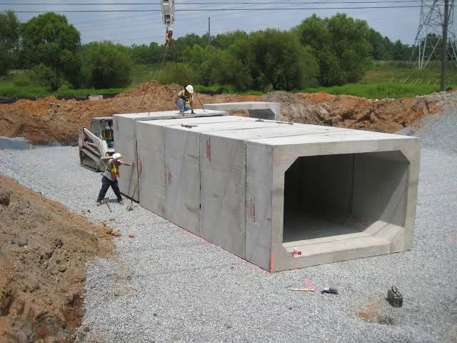
A precast box culvert is a buried rectangular concrete conduit, cast in sections at a plant and set in a trench. Four numbers decide it: span, rise, length, and fill height. Everything else on the submittal follows from those four.
This page is written for the person filling out the drawing. It covers sizing, cover limits, design load, bedding, joints, lifting and the information a plant needs to price the order.
What a box culvert section is
A box section is a single precast unit with two walls, a top slab and a bottom slab cast monolithically. Sections butt together end to end to make the barrel length. A three-sided structure is the related product: walls and a top slab, no bottom slab, set on cast-in-place footings.
Box sections carry load as a rigid frame. That matters for the spec. The barrel is a structure, not a pipe, so it is designed under bridge rules rather than drainage-pipe rules.
In Canada, design follows the Canadian Highway Bridge Design Code, CSA S6. Production, storage and cast-in hardware follow CSA A23.4. Welding of reinforcing bars follows CSA W186. The Canadian Concrete Pipe and Precast Association’s box culvert guideline cites all three.
US product standards appear on many Alberta drawings as well. ASTM C1433 covers box sections for stormwater, industrial waste and sewage. ASTM C1504 covers three-sided structures. Which standard governs is a project specification decision, not a plant decision. Name it on the drawing.
Span, rise and length
Span is the clear horizontal opening. Rise is the clear vertical opening. Length is the barrel dimension, built up from section lengths.
Sizes come in three tiers. The figures below are the reference ranges published by the Canadian and US associations. Project drawings and the governing specification set the actual available set.
| Tier | Span | Rise | Notes |
|---|---|---|---|
| Standard (CCPPA reference set) | 1800, 2400, 3000 mm | 900 to 2400 mm | Nine sizes in the published table |
| Large | 3600 to 6000 mm | 1500 to 3000 mm | Design submittal expected |
| Custom | Over 6000 mm | Over 3900 mm | Project-specific design |
| Three-sided | 8 ft to 48 ft span | Varies | No bottom slab; cast-in-place footings |
Increments are not free. Span and rise step in 300 mm. Wall and slab thickness steps in 50 mm. The US reference set runs 3 ft by 2 ft up to 12 ft by 12 ft in one-foot steps, in 6 ft and 8 ft section lengths.
Pick a standard span before you draw a custom one. A standard size runs on existing forms. A custom size does not.
Fill height drives the whole design
Fill height is the depth of material over the top slab. It is the number that most often sends a drawing back.
Two thresholds matter.
Shallow cover. Less than 0.6 m over the top slab is shallow. The CCPPA guideline treats that case as requiring mitigation, typically a concrete distribution slab, citing CHBDC Clause 7.8.1.7. Mechanical shear plate connections between sections are the alternative. Alberta’s own culvert guideline reaches the same mitigation: where cover criteria cannot be met, a concrete distribution slab may be required.
One caution on reading the Alberta document. Its minimum-cover rule, the greater of the CHBDC requirement or 600 mm measured from the crown to the edge of the shoulders, sits in a clause that states the cover recommendations do not apply to concrete structures. For a concrete box, take minimum cover from CHBDC and from the box design itself. Do not lift the metal-pipe number onto a concrete drawing.
Maximum cover. There is no single ceiling. Cover capacity is a design output, not a product property. The published design earth cover for the standard Canadian reference sizes shows how fast it moves with span:
| Span | Published design earth cover |
|---|---|
| 1800 mm | 5.5 m |
| 2400 mm | 3.6 m |
| 3000 mm | 3.6 m |
Deeper is available by design. The US product reference states boxes can be set with zero to 100 ft of cover. Reinforcement and slab thickness do the work. Give the plant the real fill height and the real surcharge, including construction equipment crossing during backfill, and the design follows.
Live load in Alberta is CL-800
Alberta does not design to the CL-625 truck that appears in the national code’s base case. The province’s culvert guideline is explicit: unless noted otherwise, the design live load is CL-800 plus Dynamic Load Allowance. Alberta’s Bridge Structures Design Criteria applies the CL-800 truck to highway bridges and to fatigue design for new highway bridges.
Carry that onto the drawing. A box designed to a lighter truck is the wrong box, and the error does not show up until the review.
Two more Alberta thresholds worth knowing at the concept stage:
- Design life. Alberta’s Bridge Structures Design Criteria sets a 75-year minimum design life for bridges including bridge size culverts, in Section 5.1 of the 2017 edition. Confirm against the current version.
- Geotechnical trigger. A proposed culvert over 4.5 m equivalent diameter triggers a geotechnical investigation under the provincial culvert guideline. Large boxes reach that threshold.
Bedding, backfill and a dry trench
Bedding is a granular layer, compacted and set to grade. Its job is to level the section and to cover hard points so the bottom slab bears uniformly.
Thickness and compaction are specification items. Neither the Canadian guideline nor the provincial culvert guideline publishes a single number for concrete boxes; both route it to the governing construction specification. Put the thickness, the gradation and the compaction target on the drawing.
The installation sequence is fixed:
- Excavate and keep the trench dry. Dewater if needed.
- Place and compact the bedding, graded to the invert.
- Set the first section groove end first.
- Set each following section with its tongue into the previous groove.
- Backfill evenly on both sides, in the layer depths the specification allows.
Uneven backfill is the common field failure. The barrel is a frame. Loading one side ahead of the other racks it.
Joints: what seals, and what does not
Joints are profile joints, tongue and groove. Butt joints exist and are used where the specification calls for them.
Sealing is a separate decision from the joint profile, and the options are not equivalent:
| Sealing method | Standard | What it achieves |
|---|---|---|
| Rubber gasket, single offset, pre-lubricated | Placed on the spigot end | Primary joint seal |
| Butyl or bitumen mastic, cold applied | ASTM C990 | Soil-tight only; requires a joint gap |
| External joint wrap | ASTM C877 | Added barrier over the completed joint |
| Non-shrink cement mortar | Per specification | Used where the specification names it |
| Geotextile strip over buried joints | 600 mm wide, centred on the joint | Default unless specified otherwise |
Two dimensional limits control acceptance. Maximum joint gap is 20 mm. For multi-cell installations, the gap between adjacent barrels is 60 mm plus or minus 10 mm, grout-filled.
If the crossing has to be watertight rather than soil-tight, say so on the drawing. Mastic alone will not get there.
Lifting and setting
Lifting hardware is cast in. Proprietary lift anchors are set in the top slab face, with additional anchors added as the unit requires.
Rig geometry is a design condition, not a field preference. The guideline asks that lift points form an equilateral triangle, or that the contained angles be equal. A spreader beam is used where the geometry needs it.
Anchor capacity is not a single rating. It is reduced by embedment length, edge distance, concrete strength at the time of lift, the rigging itself, sling angle and dynamic loads. A crew that flattens the sling angle to clear an obstruction has changed the capacity.
Width is the other setting constraint, and it is settled before the truck is loaded. Section width sets the permit class, the escort requirement and the delivery window.
Quality: what the plant proves
Acceptance rests on measurable items, and they are worth knowing before the inspection:
| Item | Requirement |
|---|---|
| Concrete cover, welded wire reinforcement | 40 mm ± 5 mm |
| Concrete cover, reinforcing bars | 50 mm ± 15 mm |
| Dimensional tolerances | Per CSA A23.4 |
| Crack rejection | Cracks wider than 0.3 mm, or full-depth cracks |
| Core sampling method | CSA A23.2-14C |
We cast to those numbers and document them. Ask for the records with the submittal, not after delivery.
Ordering: what the plant needs
Send these and a box culvert can be priced and scheduled. Leave one out and the quote carries an assumption:
- Span, rise and total barrel length
- Number of cells
- Fill height over the top slab, minimum and maximum along the barrel
- Design live load, and confirmation of CL-800 plus Dynamic Load Allowance if provincial
- Governing design code and product specification
- Skew, if any, and the end condition being used
- Joint type and the required sealing method, soil-tight or watertight
- Bedding specification: material, thickness, compaction target
- Site access: crane position, working width, approach grade
- Required delivery window
Lead time
Lead time on a box culvert is set by four things, in roughly this order: design submittal and engineering review, form availability for the span and rise chosen, whether the size is standard or custom, and transport width.
The first and the last move most. A standard span with a clean submittal schedules against existing forms. A custom size adds design and form work. An over-width section adds permit and escort time, independent of how fast the plant casts it.
Send the drawing early. The review cycle is the part nobody can compress at the end.
Where this article stops
This page covers the barrel: sizing, cover, load, bedding, joints, lifting, acceptance and ordering.
It does not cover end treatment. Headwalls, end-treatment thresholds, skew limits and bevel geometry are a separate decision with their own provincial thresholds, and they are treated separately. It does not cover hydraulic sizing, fish passage, or the flow calculation that decides the opening in the first place. Those are the designer’s inputs, and they arrive before the box is specified.
It also does not cover three-sided structures beyond the span range. Footing design controls that product.
For the broader civil product range, see precast concrete in infrastructure. For surface drainage rather than a buried crossing, see precast trench drain load class and slope. For a plain-language starting point, see what precast concrete is. For the full civil and municipal product list, see our solutions.
FAQ
What is the minimum cover over a precast box culvert? Less than 0.6 m over the top slab is treated as shallow cover, and it typically requires mitigation such as a concrete distribution slab, citing CHBDC Clause 7.8.1.7. Mechanical shear plate connections are the alternative. Minimum cover for a concrete box comes from CHBDC and the box design, not from the metal-pipe cover rule in the provincial culvert guideline.
What design live load applies to a culvert in Alberta? CL-800 plus Dynamic Load Allowance, unless the project notes otherwise. The provincial culvert guideline states it directly.
How deep can a box culvert be buried? There is no single maximum. Cover capacity is a design output. The published design earth cover for the standard Canadian reference sizes is 5.5 m at an 1800 mm span and 3.6 m at 2400 and 3000 mm spans, and the US product reference states boxes can be set with zero to 100 ft of cover when designed for it.
What standard sizes are available? The Canadian reference set lists spans of 1800, 2400 and 3000 mm with rises of 900 to 2400 mm. Large boxes run 3600 to 6000 mm span. Span and rise step in 300 mm; wall and slab thickness steps in 50 mm.
Are box culvert joints watertight? Not automatically. A rubber gasket on the spigot end is the primary seal. Butyl or bitumen mastic to ASTM C990 is soil-tight only and requires a joint gap. External joint wrap to ASTM C877 adds a barrier. Specify watertight explicitly if the crossing needs it.
What is the maximum joint gap? 20 mm. For multi-cell installations, the gap between adjacent barrels is 60 mm plus or minus 10 mm, grout-filled.
Does a box culvert count as a bridge in Alberta? Bridge size culverts are covered by the province’s bridge documents, and the Bridge Structures Design Criteria sets a 75-year minimum design life for bridges including bridge size culverts. A culvert over 4.5 m equivalent diameter also triggers a geotechnical investigation under the provincial culvert guideline.
What does the plant need to quote? Span, rise, length, cell count, fill height range, design live load, governing specification, joint and sealing requirement, bedding specification, site access and the delivery window. Send drawings and we will return a spec sheet, a submittal package and a quantity price.
Sources
- Alberta Transportation, Design Guidelines for Bridge Size Culverts: https://www.transportation.alberta.ca/content/doctype30/production/dsngdlclvapril2012.pdf
- Alberta, Bridge Structures Design Criteria (current version): https://open.alberta.ca/publications/bridge-structures-design-criteria-version-8-1
- Canadian Concrete Pipe and Precast Association, Precast Box and Culvert Guideline: https://ccppa.ca/wp-content/uploads/2018/11/PrecastBoxCulvertGuideline_final_draft.pdf
- National Precast Concrete Association, box culvert product reference: https://precast.org/wp-content/uploads/092923_Products_BoxCulvertPresentation.pdf